|


| |
GN Electric Operations continued
OPERATION
6. Separate excitation can be established at any speed
to obtain either tractive effort or braking effort. This is
explained in the section titled "Separate Excitation".
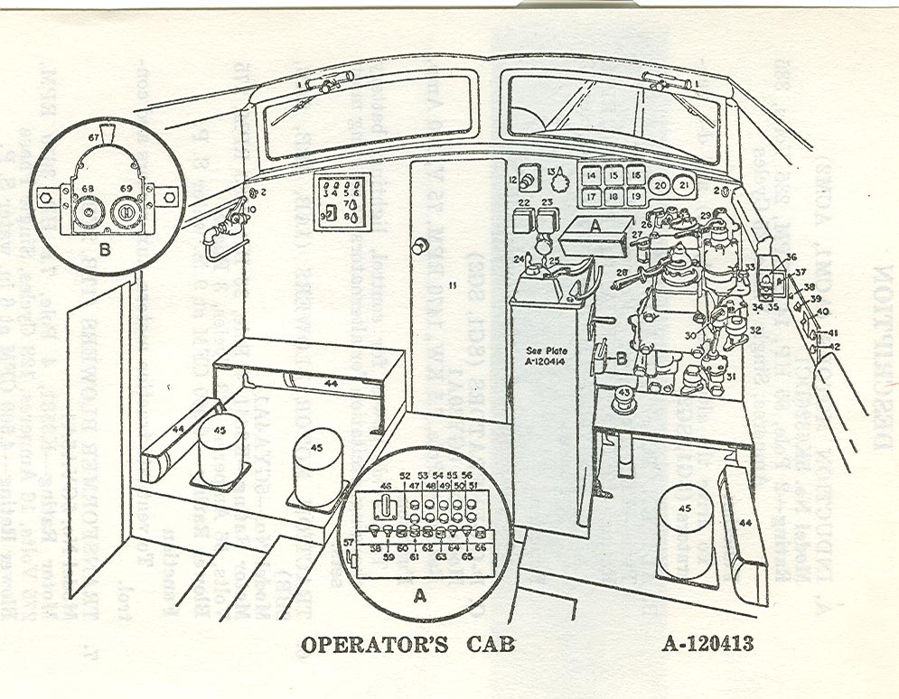
NOTE: It should be determined which traction motor
circuit will provide the highest reading on the
TRACTION MOTOR ARM. AMPS. meter. This
can be done by moving the Meter Transfer
Switch (Item 46, Plate A-120413)
from one motor
combination to another until the highest reading
is obtained. This combination should be used for
metering purposes to prevent overloading the
remaining traction motors.
SEPARATE EXCITATION
A. GENERAL
At any locomotive speed or from a standstill the Main
Handle and Separate Excitation Handle can be positioned,
by manipulation, to establish separate excitation. Once
this is established the Separate Excitation Handle can be
moved to provide either regenerative braking or tractive
effort and the Main Handle will provide a medium of
control for the condition selected by the Separate Excitation
Handle.
Also, for the condition selected above, the Main Handle
may be left in one position and the Separate Excitation
Handle provide the medium of control.
Generally speaking, separate excitation connection is to
be established from standstill when the locomotive starts
on a downgrade. However, the locomotive can start in
motoring from a standstill, in separate excitation,
provided the load is not so heavy as to cause too high currents
in traction motor circuits or synchronous motor.
Page 97
OPERATION
CAUTION: There is a red arrow on the "AMPS. FIELD
TRACTION MOTOR" meter at 1067 amperes
which indicates the maximum field current
which should be used in Separate Excitation.
A pair of red arrows on the "TRACTION
MOTOR ARM. AMPS." meter indicate the
continuous current for use in the High Speed
Connection either motoring or regenerating.
The above paragraph will be further clarified in the
following phases of operation, but the operator must learn
from experience the characteristics involved with the
operation.
B. ESTABLISHING SEPARATE EXCITATION
1. Move Separate Excitation Handle from Off to E notch
and leave handle in this position until the SEP EXC
indicating light comes on. This light indicates that the
regenerative exciter is connected in series with the traction
motor circuits.
2. Then advance the Separate Excitation Handle until
the pointer on the EQUALIZING VOLTS meter is at 0 or
within the white portion of the band.
3. Close the SEP EXC button which connects the field
shunting resistors in the circuit.
4. For starting locomotive in separate excitation:
a. Move main handle to notch No. 1
b. Move Separate Excitation Handle to notch E and
wait for SEP EXC light to come on. Then advance
Separate Excitation Handle to notch No. 1 and push
the SEP EXC Button.
c. Advance Separate Excitation Handle and release
brakes. If on a down grade, build up a strong field
by further advancing Separate Excitation Handle,
Page 98
OPERATION
d. If motoring is desired, advance Main Handle. Then
manipulate both handles to get desired speed and
tractive effort.
C. USING SEPARATE EXCITATION
1. Braking Effort
a. When separate excitation has been established,
regenerative braking can be obtained by notching
out the Separate Excitation Handle until the desired
braking effort is selected for any given notch of the
Main Handle.
b. The Main Handle may now either increase or
decrease the braking effort selected by the Separate
Excitation Handle, thus:
By notching Off the Main Handle, braking effort
is increased and by notching out the effort is
decreased.
c. Also, for any given position of the Main Handle
while regenerating, the Separate Excitation Handle
can increase or decrease braking effort, thus:
By notching Off the effort is decreased and by
notching out effort is increased.
2. Tractive Effort
a. If tractive effort is desired after separate
excitation has been established, the Separate Excitation
Handle should be notched Off until the desired
effort is obtained for a given notch of the Main
Handle.
b. The Main Handle may now either increase or
decrease tractive effort in the position selected by the
Separate Excitation Handle, thus;
By notching out, the tractive effort is increased
and by notching Off, it is decreased.
Page 99
OPERATION
c. Also, for any given position of the Main Handle
while motoring in separate excitation, the Separate
Excitation Handle can increase or decrease tractive
effort.
By notching Off the Separate Excitation Handle,
tractive effort is increased, and by notching Out it
is decreased.
D. RE-ESTABLISHING SERIES MOTORING
1. While motoring, manipulate the Main Handle and
Separate Excitation Handle until the AMPS FIELD and
TRACTION MOTOR ARM AMPS meters have the same
reading.
2. Then push the SELF EXCITATION (series) switch
button.
3. Slowly notch off Separate Excitation Handle until
the SEP EXC lamp goes out. Then move Sep. Exc. Handle
to the Off position.
IMPORTANT
Once the Self Excitation button has been pushed, it is
necessary to go through the full procedure in order to
return to Separate Excitation again.
NOTE: In an emergency, a quick way to remove power
(including regenerative braking) from your
traction motor circuits is either to trip your
CONTROL breaker, or pull the JR HOLD button.
Remember, however, that when this is done, you
will have only your air brakes to control your
train.
Page 100
 
 
|